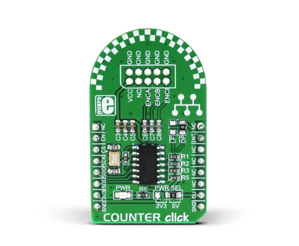
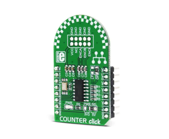
Counter Click is a compact add-on board that allows you to add a quadrature counter to your design. This board features the , a 32-bit quadrature counter with a serial interface from LSI Computer Systems. The LS7366R reads the incremental encoder A and B pulses over unpopulated ten pins header, which are out of phase to each other, ideally by 90°. By decoding them, the LS7366R can determine the direction and speed of the shaft. This Click board™ makes the perfect solution for measuring RPM and speed of DC motor shafts, reading incremental encoders, and more.
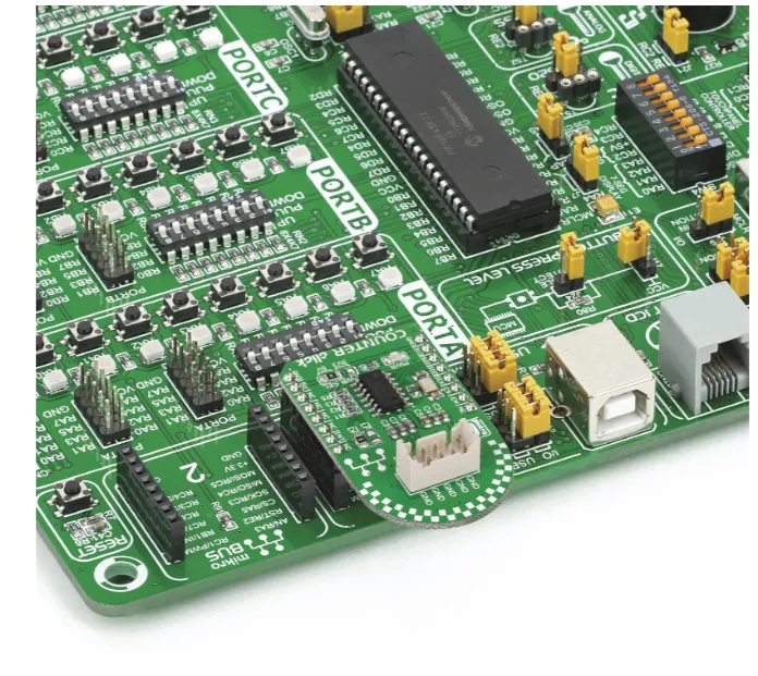
Counter Click is supported by a compliant library, which includes functions that simplify software development. This comes as a fully tested product, ready to be used on a system equipped with the socket.
HOW DOES IT WORK?
Counter Click is based on the LS7366R, a 32-bit quadrature counter with a serial interface from LSI Computer Systems. It is a CMOS counter with a direct interface for quadrature clocks from incremental encoders. It also interfaces with the index signals from incremental encoders to perform various marker functions. This counter can be configured to operate as a 1, 2, 3, or 4-byte counter. It can also be programmed to work in several counting modes such as Modulo-N, Non-recycle, Range-limit, or Free-running mode.
This Click board™ features a 2x5 header (2.54mm pitch) with pins to interface the LS7366R inputs, VCC, and a few GNDs, which are basically the power supply pins of the Click board™ itself. The VCC and GND pins can power the quadrature incremental encoder. This header also includes ENCA and ENCB, the input A and B pins of the LS7366R, to directly apply the quadrature clock outputs from incremental encoders on them, and Index (ENCI) pin, a programmable input driven directly by an incremental encoder's index output.
The LS7366R uses a standard 4-wire SPI serial interface to communicate with the host MCU over the mikroBUS™ socket. The counter is enabled when EN input is in a high logic state; otherwise disabled with low logic level. In addition, this Click board™ features interrupt over INT pin that can be configured to use LFLAG or DFLAG over the LF and DF solder jumpers with DFLAG set by default. This way, users can choose LFLAG, an open drain latched output, or DFLAG, an instantaneous push-pull output, thus using these outputs to flag Carry, Borrow, Compare, and Index occurrences.
This Click board™ can operate with either 3.3V or 5V logic voltage levels selected via the PWR SEL jumper. This way, both 3.3V and 5V capable MCUs can use the communication lines properly. However, the Click board™ comes equipped with a library containing easy-to-use functions and an example code that can be used, as a reference, for further development.
SPECIFICATIONS
| Type | Rotary encoder |
| Applications | Can be used for measuring RPM and speed of DC motor shafts, reading incremental encoders, and more |
| On-board modules | LS7366R - quadrature counter from LSI Computer Systems |
| Key Features | 32-bit counter, programmable functional modes, SPI serial interface, A and B pins for quadrature clock outputs from incremental encoders, index signal directly from incremental encoders, ability to use Carry/Borrow/Compare/Index flag occurrences, low power consumption, and more |
| Interface | GPIO,SPI |
| Compatibility | mikroBUS |
| Click board size | M (42.9 x 25.4 mm) |
| Input Voltage | 3.3V or 5V |
PINOUT DIAGRAM
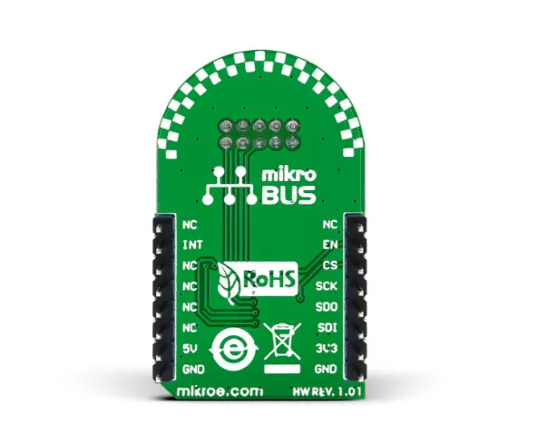
This table shows how the pinout on Counter Click corresponds to the pinout on the mikroBUS™ socket (the latter shown in the two middle columns).
| Notes | Pin | Pin | Notes | ||||
|---|---|---|---|---|---|---|---|
| NC | 1 | AN | PWM | 16 | NC | ||
| Count Enable | EN | 2 | RST | INT | 15 | INT | Interrupt |
| SPI Chip Select | CS | 3 | CS | RX | 14 | NC | |
| SPI Clock | SCK | 4 | SCK | TX | 13 | NC | |
| SPI Data OUT | SDO | 5 | MISO | SCL | 12 | NC | |
| SPI Data IN | SDI | 6 | MOSI | SDA | 11 | NC | |
| Power Supply | 3.3V | 7 | 3.3V | 5V | 10 | 5V | Power Supply |
| Ground | GND | 8 | GND | GND | 9 | GND | Ground |
ONBOARD SETTINGS AND INDICATORS
| Label | Name | Default | Description |
|---|---|---|---|
| - | PWR | - | Power LED Indicator |
| - | PWR SEL | Right | Logic Level Voltage Selection 3V3/5V: Left position 3V3, Right position 5V |
| LF | LF | Unpopulated | Open Drain Latched Programmable Interrupt Jumper |
| DF | DF | Populated | Instantaneous Push-Pull Programmable Interrupt Jumper |
COUNTER CLICK ELECTRICAL SPECIFICATIONS
| Description | Min | Typ | Max | Unit |
|---|---|---|---|---|
| Supply Voltage | 3.3 | - | 5 | V |
| Resolution | - | 32 | - | bit |
| Count Frequency | - | - | 40 | MHz |
SOFTWARE SUPPORT
We provide a library for the Counter Click as well as a demo application (example), developed using Mikroe . The demo can run on all the main Mikroe .
Package can be downloaded/installed directly from NECTO Studio Package Manager (recommended), downloaded from our or found on .

